Arcarix Studio · AI DEVELOPMENT APPROACH Planned
AI for electronics, code and enclosure design.
Arcarix Studio is an AI prototyping system in development, connecting requirements, electronics, firmware and enclosures. Its aim is to identify missing details and carry design changes across disciplines, reducing repeated work. Explore the workflow today through an example-based demo.
PLATFORM FEATURES
Tools for each part of development
Explore the platform under development. Each feature identifies what you can try in the demo and what is planned.
Idea to requirements Next milestone
The planned workflow starts with the customer and use case, then structures functional, environmental, power and quantity requirements through follow-up questions.
- Claude
- Structured requirements · Missing-detail questions · Draft test criteria
- Tools
- Requirements schema checks
- Output
- Requirements spec · Acceptance criteria
You confirm the requirements
Review requirements from a product brief and adjust the example settings in the demoChips & components Planned
Compare MCU, sensor and power candidates against the requirements, with datasheet sources. Every choice records its reason, its alternatives and what to recheck if it changes.
- Claude
- Candidate comparison · Rationale and alternatives
- Tools
- Parts catalog · Voltage, pin and address rules
- Output
- BOM · Pin map · Interface definition
Firmware Next milestone
Draft firmware from the confirmed requirements, compile it on a pinned toolchain, read the compiler output, fix and rebuild.
- Claude
- Code drafts · Compiler-error fixes · Change explanations
- Tools
- Isolated build workers · Pinned toolchains
- Output
- Source · Build logs · Build record
Your approval before flashing a device
The demo shows a firmware skeleton and an example build log per chip and sensorVirtual hardware Planned
Run the firmware on an emulated board with sensor models before buying hardware. Check boot, communication and fault handling virtually and keep the logs.
- Claude
- Read simulation logs · Explain failures
- Tools
- QEMU-class virtual boards · Peripheral models
- Output
- Simulation logs · Check results
Enclosure & prototype Planned
Generate a parametric enclosure around the board, sensor airflow and connector access, then move to a 3D-printed or CNC prototype.
- Claude
- Mechanical constraints · Geometry parameters
- Tools
- Parametric CAD · Fit and clearance checks
- Output
- CAD and drawings · Prototype process spec
Sourcing & manufacturing Planned
Check supply and alternatives for the approved BOM, then build a quote package with process, quantity and inspection terms and connect it to manufacturers.
- Claude
- Supply-risk summary · RFQ drafting
- Tools
- Supplier lookup · Quote-request dispatch
- Output
- Sourcing review · RFQ package · First-article criteria
Your approval before anything goes to a supplier
The demo shows a BOM, production line and illustrative estimate; inquiries are open by emailREFERENCE PROJECT Live
Example electronics for a site-monitoring sensor
Even a simple USB-powered temperature and humidity monitor ties together power, communication, sampling and sensor exposure. Switch between interfaces, firmware and review items.
- Environment
- Indoor · non-condensing
- Measurement
- Temperature · RH · 30 s
- Interface
- I²C · 3.3 V
- Evidence
- Example, not bench-tested
CHANGE IMPACT
What changes when a different board is selected
Keep the same I²C sensor and a new board still changes pin mapping, build target and mounting dimensions. Compare the affected items in the example below. The planned platform will track these changes within each project.
Switch between ESP32 and Pico W.
SDA → GPIO21
SCL → GPIO22
TARGET → ESP32SDA → GPIO21
SCL → GPIO22
TARGET → ESP32Preset example of change impact. It does not execute engineering tools or verify compatibility.
 96 × 66 × 28 mm
ASSUMED ENVELOPE
- VentilationSensor exposure and heat
- ElectronicsComponent height and ports
- EnclosureFastening and assembly
ENCLOSURE Planned
Enclosure design for installation and assembly
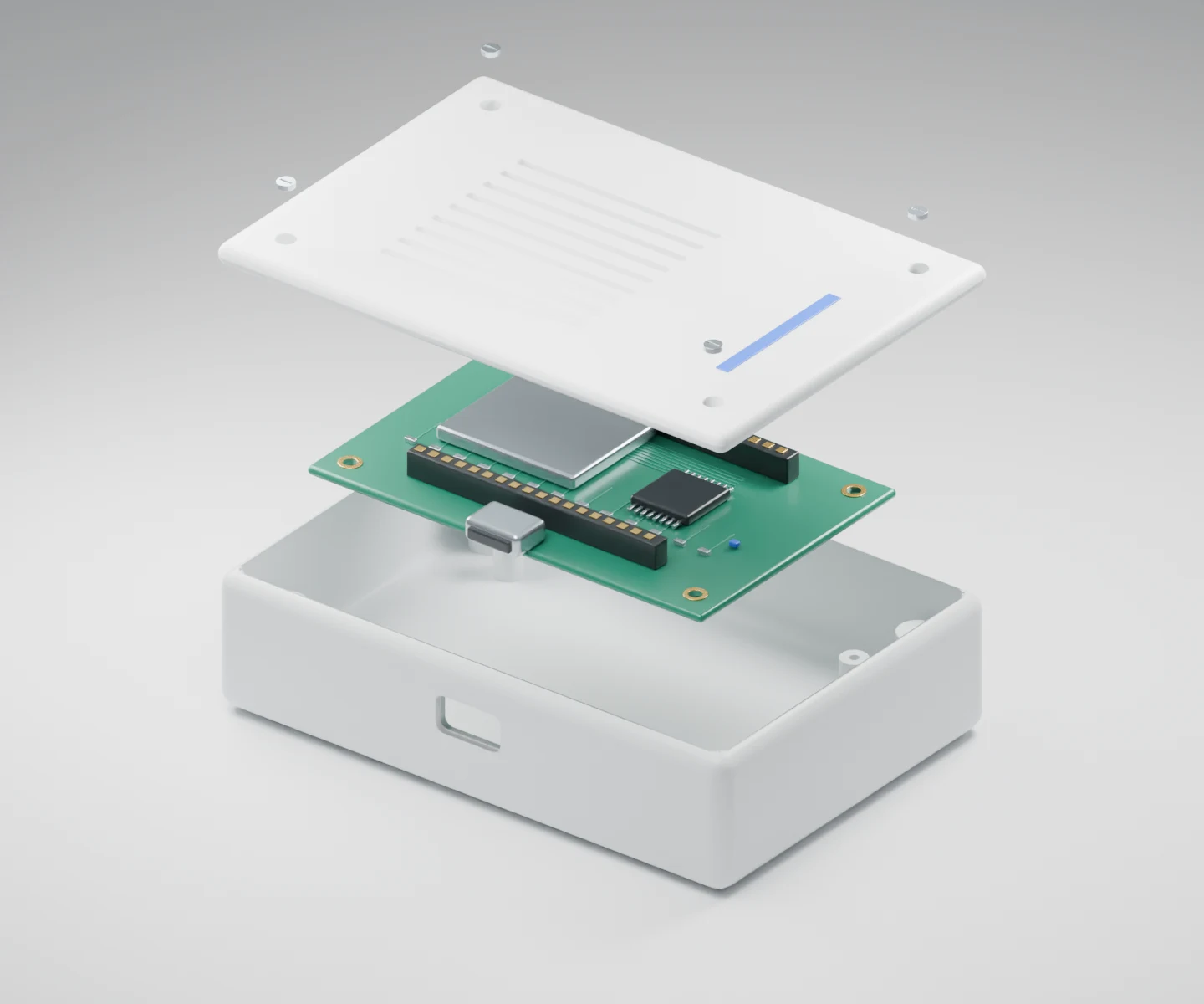
Vent placement allows the sensor to sample ambient air. Connector access, cable clearance and screw positions affect assembly. Mechanical design also needs to account for the use environment, appearance, servicing and manufacturing process.
An exterior design study for an environment sensor. Switch between assembled and exploded views to inspect the structure.
EXPLORE AN EXAMPLE Live
Explore the example. Download the files.
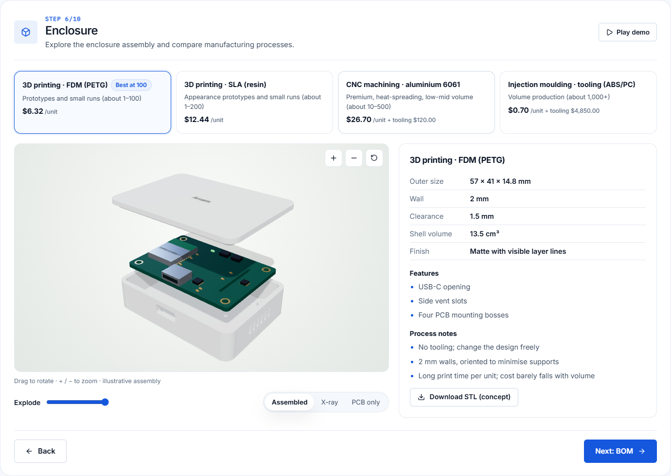
A site-monitoring sensor example from the demo, with files exported from the same settings. The files contain the product brief, component configuration, enclosure dimensions and manufacturing cost assumptions. They illustrate a design review and contain no physical test results.
Room monitor example
ESP32-C3-MINI-1 + SHT31 · 30 s · Indoor · 100 units · FDM enclosure
START A PROJECT
Tell us what you want to build.
An early idea, a design in progress or a part you need to find. Tell us where you are, and we’ll discuss the work and next steps.